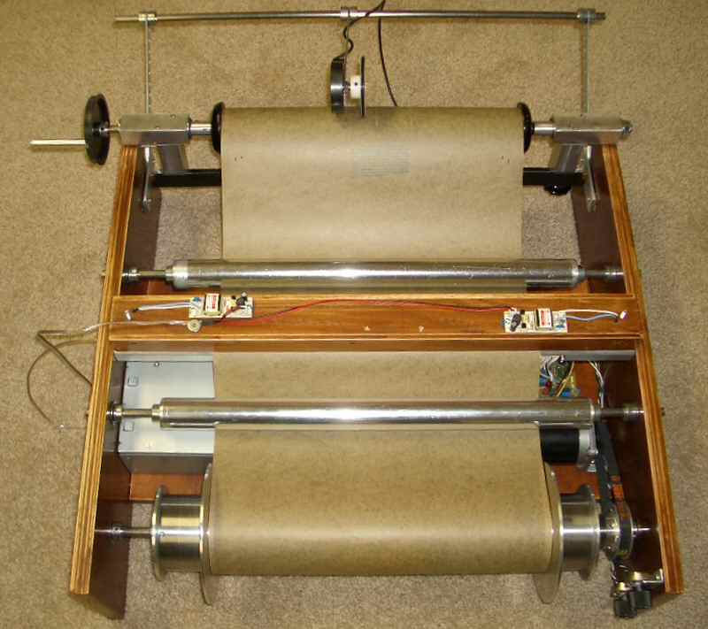
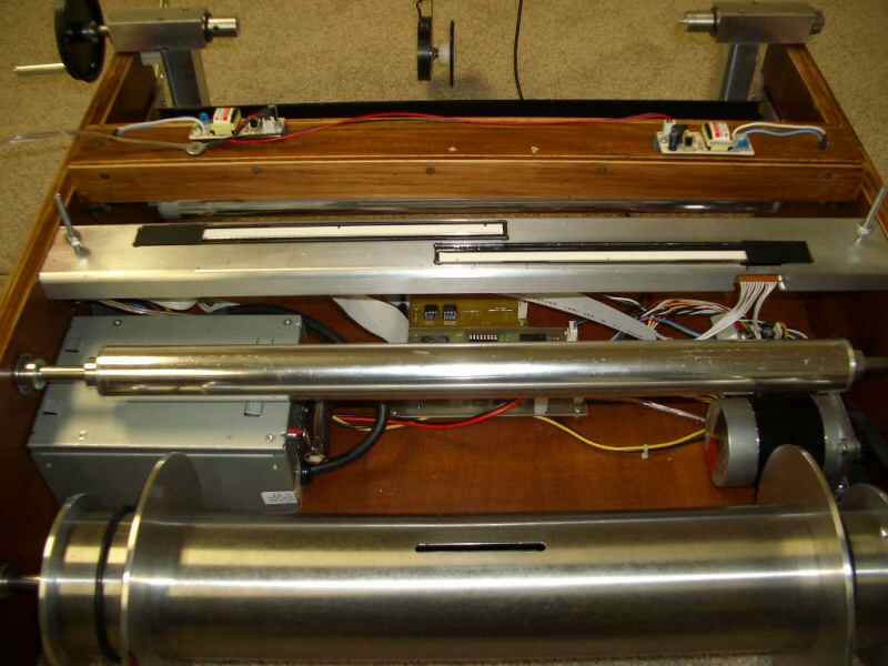
John's free-run scanner loaded with a T100 Red Welte roll. Note adjustable flanges on take-up and adjustable source chucks,
the paper path beneath a pair of rotating rollers and riding over the pair of A4 CIS sensors, optical encoder riding on the source roll,
and the ccfl lamp box positioned above the A4 CIS sensors. While this scanner is aimed at rolls wider than 11 1/4",
it can also accept rolls 11 1/4" and and down to 10 1/8" (58n rolls).
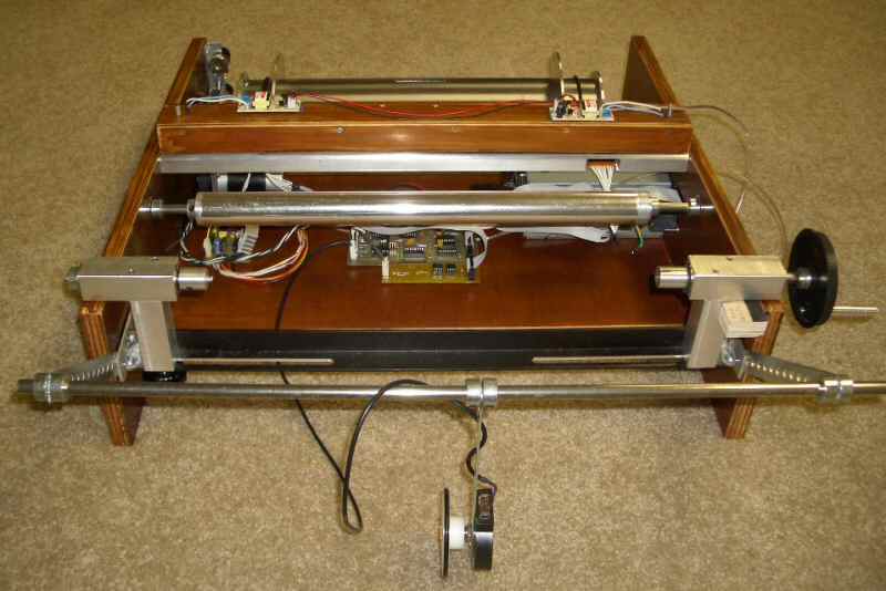
Here can be seen the electronics located beneath the A4 CIS sensors, and the optical encoder swung away to facilitate roll changing.
The adjustable source roll chucks are mounted on a carrier rod so they may be moved from side to side for varying width rolls.
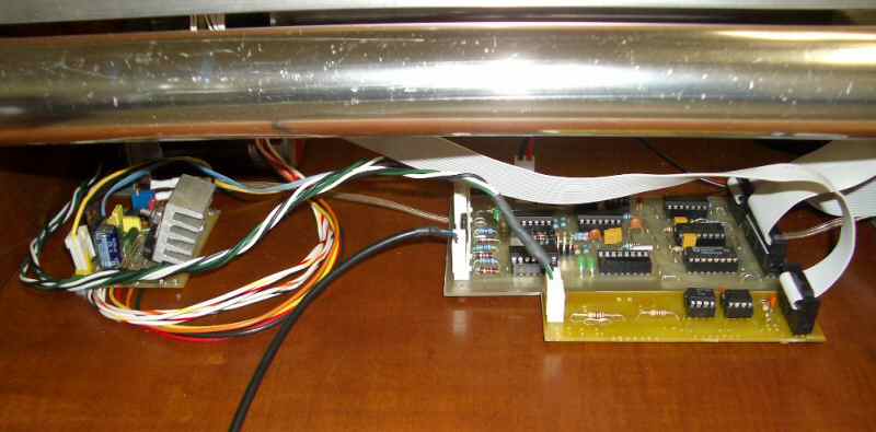
This close-up of the electronics shows the marriage of a MK3a board with an abbreviated Mk3 board.
The additional Mk3 board is needed for the data coming off the second A4 CIS sensor.
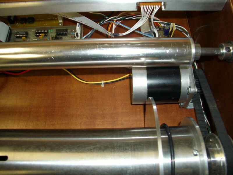
Close-up of the stepper motor and notched drive belt. Note also the adjustable take-up flanges held in place with simple "O" rings.
Good view of the A4 CIS twin array, mounted outside-in. The ccfl lamp box is a simple container with a pair of lamps physically mounted
in a pair of notches. At roughly mid-point inside the box, are longitudinal grooves containing needed layers of neutral density filter.
The lamp box is simply located on a pair of positioning pins to facilitate roll changing. The two inverters needed to power the ccfl lamps
are positioned for minimum wire length. Note the conventional computer power
supply, providing all the power requirements.
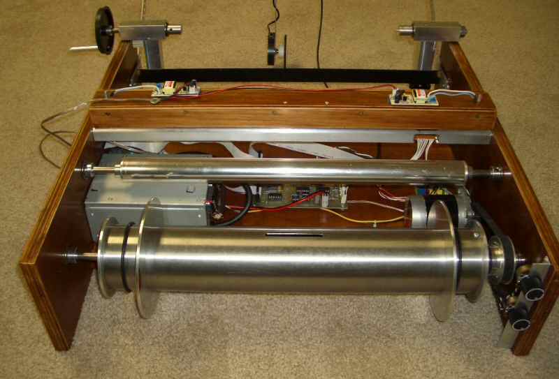
To the right front can be seen the two 10-turn pots for adjusting the "brightness" of the ccfl lamps. It is of critical importance
to acquire an image with as even exposure, both sides, as possible. Requires some experimentation to arrive at a setting suitable
for both original rolls and new translucent recut rolls.
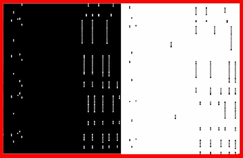
A fragment of a T100 Red Welte roll, as seen through Anthony Robinson's CISVIEWER. The "outside-in" physical configuration
of the CIS sensors results in 1/2 of the data reversed and must be flipped in the software. The red border is added simply for clarity.